Concept Dictionary archive — page 2
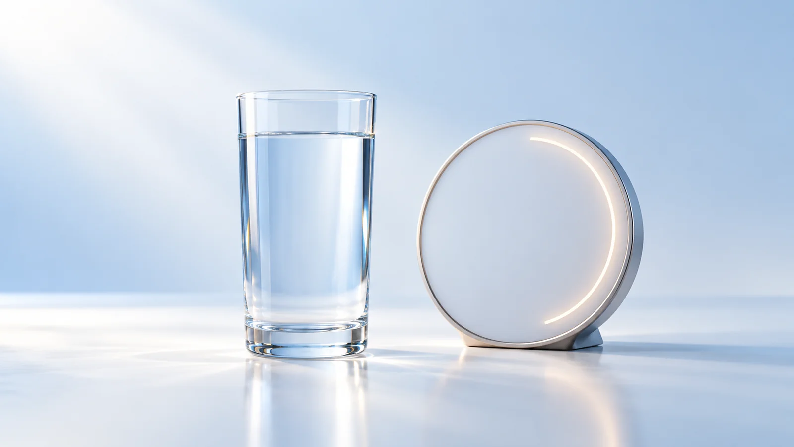
Capacity Factor and Operating Factor — energy vs time
Capacity factor = energy generated / (rating × clock hours); operating factor = on-line hours / clock hours; without above-rated output the capacity factor cannot exceed the operating factor.
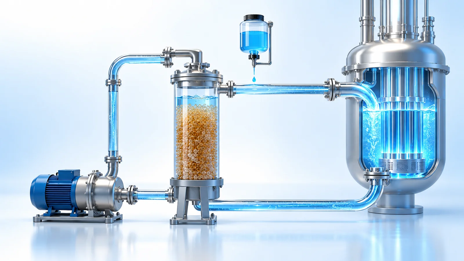
Chemical and volume control system — letdown, charging, VCT and boron control
The CVCS lets down RCS coolant, cools and purifies it and charges it back, with letdown plus seal bleed-off balancing charging, to control inventory, boron and chemistry, and supplies seal injection and auxiliary spray.
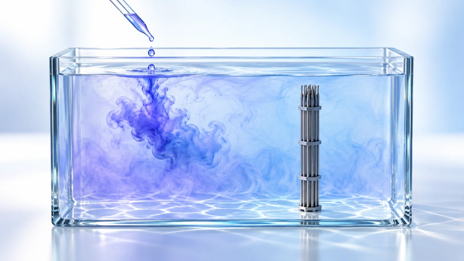
Chemical Shim — boron worth, ppm conversions and letdown curve
One-group boron worth is (Σ̄aB/Σ̄aM)(1−f₀) with Σ̄aB/Σ̄aM = 1.905×10⁻³·C; 1 ppm B = 5.72 mg H₃BO₃/kg, so 21,000 ppm B ≈ 12.0 w/o boric acid.
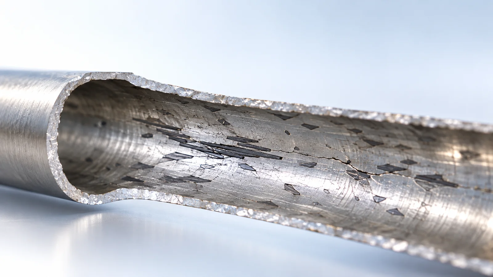
Cladding hydriding — hydrogen pickup, TSS and hydride reorientation
About 7.5 wppm of hydrogen per µm of oxide (PUF 15 %) enters the cladding; above TSS it forms δ-hydrides, and radial reorientation under hoop stress on cooling sharply cuts ductility, hence the 400 °C dry-storage limit.
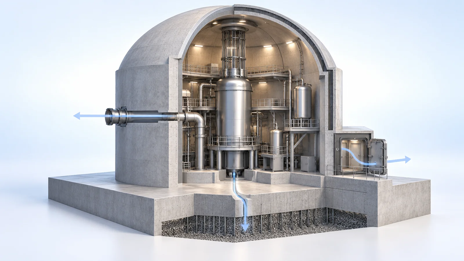
Containment failure modes — bypass, isolation failure, early, late and basemat melt-through
Containment failure modes are classified by release path and timing; early failure, bypass and isolation failure dominate LERF, while late failure and basemat melt-through leave more time for deposition.
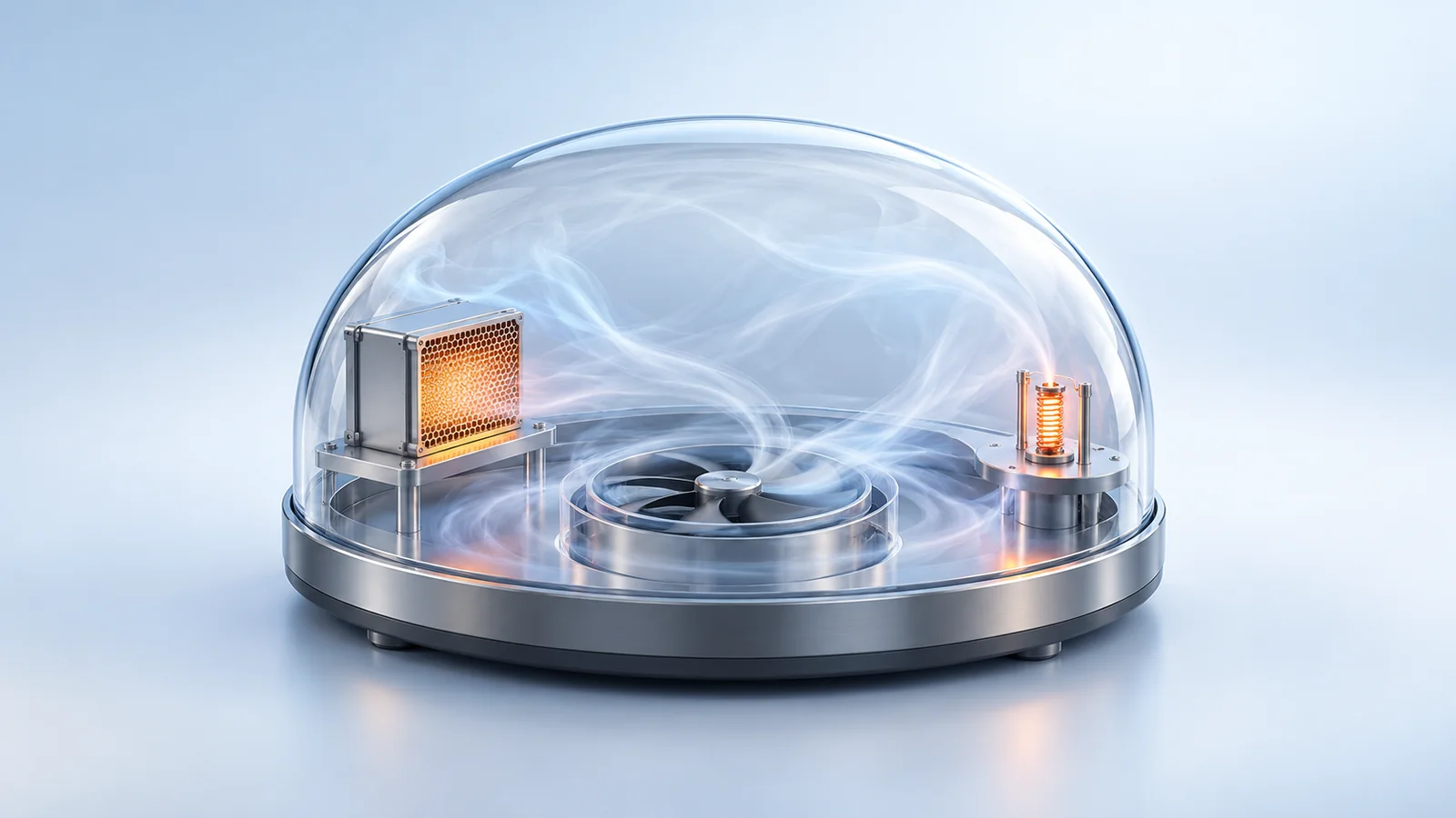
Containment hydrogen control — mixing, PARs, igniters, inerting and the 10 % criterion
Hydrogen risk is judged by how it would burn; containments are designed to keep uniform hydrogen from a 100 % cladding reaction below an average of 10 vol% using PARs, igniters or inerting.
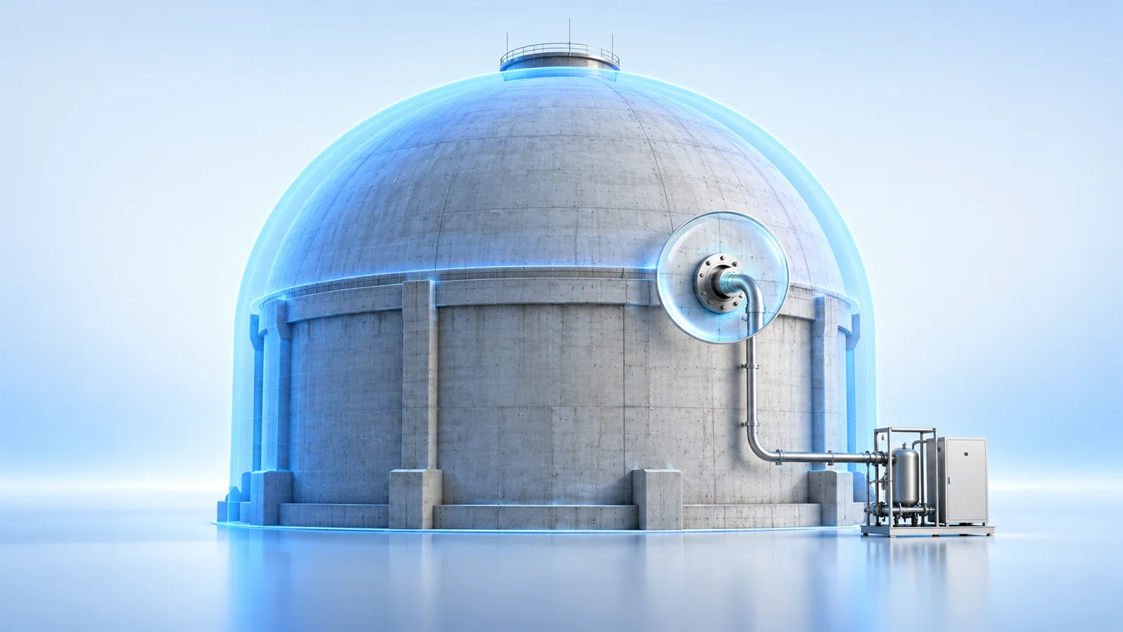
Containment Leakage Rate Test (ILRT/LLRT) — Pa, La and the 0.75 / 0.60 criteria
Type A tests the whole containment (≤ 0.75 La, mass-point L = −2400·B/A), Types B and C the penetrations and isolation valves (maximum-pathway sum ≤ 0.60 La); La is % of air mass per day at Pa.

Core Protection Calculator (CPC) — DNBR and LPD trips from ex-core signals
The four-channel CPC computes minimum DNBR and peak linear heat rate (LPD, kW/ft) in real time and trips through the PPS 2/4 logic; COLSS only monitors, and a COLSS failure is covered by CPC-channel monitoring.
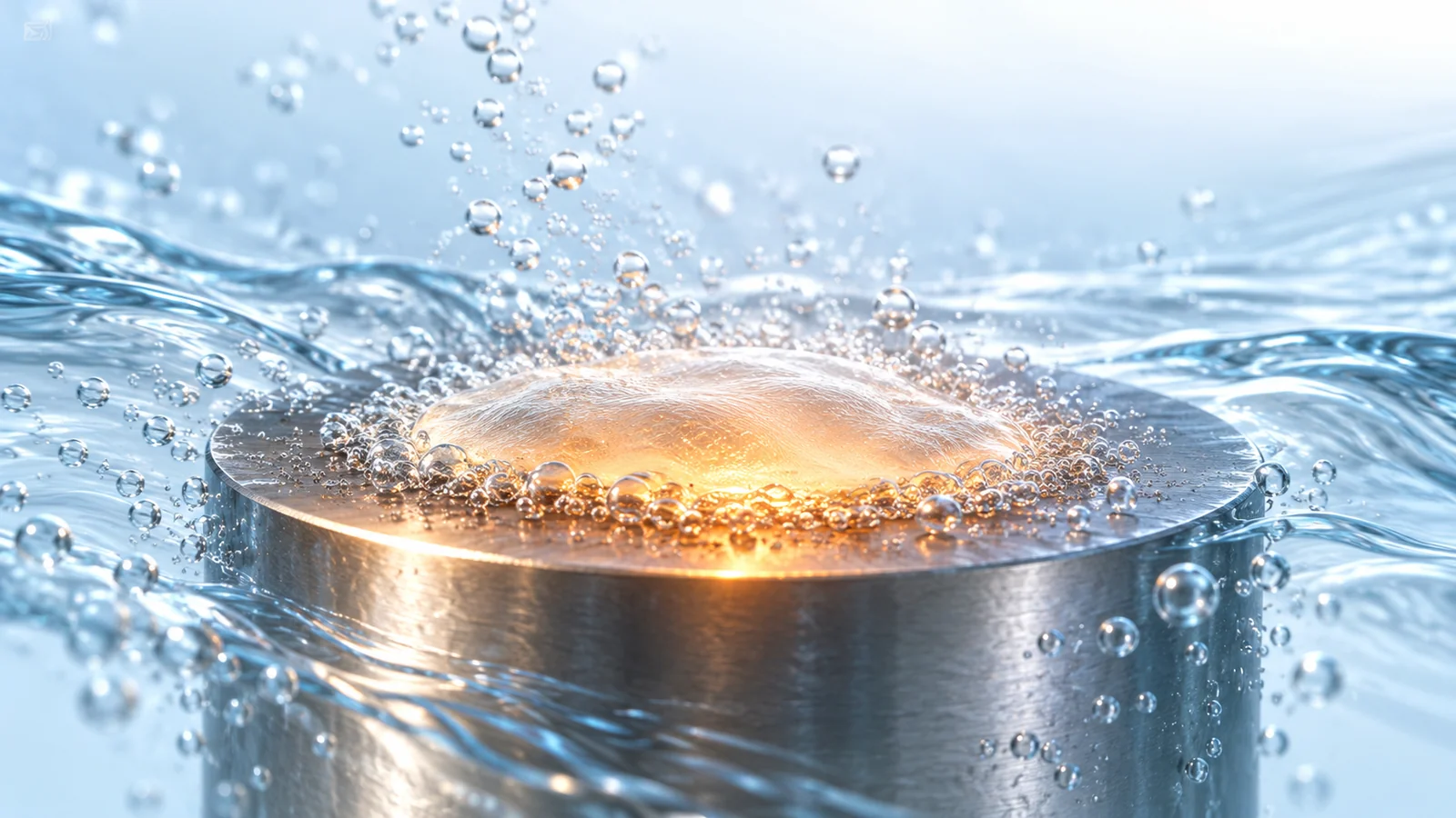
Critical Heat Flux and DNB — boiling curve, DNB versus dryout, correlations
CHF is the maximum heat flux of nucleate boiling (about 1.26 MW/m² for water at 1 atm); beyond it a heat-flux-controlled rod jumps to film boiling, which is why no DNB is a fuel design limit.

Critical safety functions — six status trees, colours and priority
The six CSFs (S, C, H, P, Z, I) are judged from measured variables on status trees; red goes to a recovery procedure at once, and colour outranks tree priority.