Waste, Fuel Cycle & Decommissioning · C-WD-005
Radioactive Waste Treatment at Nuclear Power Plants — Gaseous, Liquid and Solid Sources, Treatment Processes and Decontamination Factors
Segregated collection by form and activity, then delay, filtration, evaporation, ion exchange, compaction and solidification, ending in monitored release or disposable packages.
Radioactive waste treatment at a nuclear power plant means collecting the gaseous, liquid and solid wastes generated during operation separately by physical form and activity level, then processing them by delay, filtration, evaporation, ion exchange, compaction and solidification. The end products are either monitored releases below the effluent limits or packages that can be accepted for disposal.
In short: fission products and activation products enter the coolant and become gaseous, liquid and solid waste; gases are delayed, filtered and released under monitoring, liquids are evaporated, ion-exchanged or treated by RO and then reused or released under monitoring, and solids are volume-reduced, solidified and sent to the repository. This entry shows how that principle is implemented in real plant systems.
Principle and mechanism
How the nuclides form — three groups
The nuclides that end up in the waste fall into three groups by formation route.
| Group | Formation route | Representative nuclides |
|---|---|---|
| Fission products | Leakage through cladding defects; fission of tramp uranium contaminating the cladding surface. Cs-134 is produced mainly by Cs-133(n,γ) capture | Kr, Xe (noble gases), I-131 to I-135, Cs-137, Cs-134 |
| Activated corrosion products (CRUD) | Corrosion products from system materials are activated as they pass through the core: Co-59(n,γ)Co-60, Ni-58(n,p)Co-58 | Co-58, Co-60, Mn-54, Fe-59, Cr-51 |
| Activated coolant and additives | O-16(n,p)N-16, B-10(n,2α)H-3, Li-6(n,α)H-3, O-17(n,α)C-14, Ar-40(n,γ)Ar-41 | H-3, C-14, N-16, Ar-41 |
Part of the H-3 produced by ternary fission also permeates the cladding into the coolant. Transuranics form inside the fuel and enter the coolant in trace amounts only when fuel is defective. Most of the waste activity comes from corrosion products (Co-58, Co-60) and fission products (Cs, I). H-3 and C-14 are hardly removed by treatment, so they are managed through the amount released.
Sources — five each for gas, liquid and solid
A PWR has at least five typical sources of each physical form.
| Form | Sources | Characteristics |
|---|---|---|
| Gas | ① Degassing of the primary coolant (volume control tank purge, reactor drain tank vent) ② Containment purge and ventilation ③ Auxiliary and fuel building ventilation ④ Condenser air-ejector exhaust ⑤ Turbine gland seal and SG blowdown tank vents | ① high-activity Xe, Kr and hydrogen; ②③ iodine, particulates, H-3; ④⑤ low level in normal operation, and the monitoring point for SG tube leakage |
| Liquid | ① Excess CVCS letdown (boron dilution, volume control) ② Equipment drains ③ Floor drains ④ Chemical, decontamination and laboratory wastes ⑤ Laundry and shower wastes (+ SG blowdown and condensate demineralizer regeneration wastes) | ①② low total dissolved solids (TDS), high activity; ③ high TDS, oil; ④ acids and bases; ⑤ surfactants, low activity, large volume |
| Solid | ① Spent resin ② Spent filters (cartridge, HEPA, charcoal) ③ Dry active waste (DAW: protective clothing, plastic sheet, gloves) ④ Concentrates (evaporator bottoms) ⑤ Sludge and replaced components | ①② high activity, decay storage and shielded handling; ③ largest volume, compactible and combustible; ④ high salt, boric acid |
Treatment processes by physical form
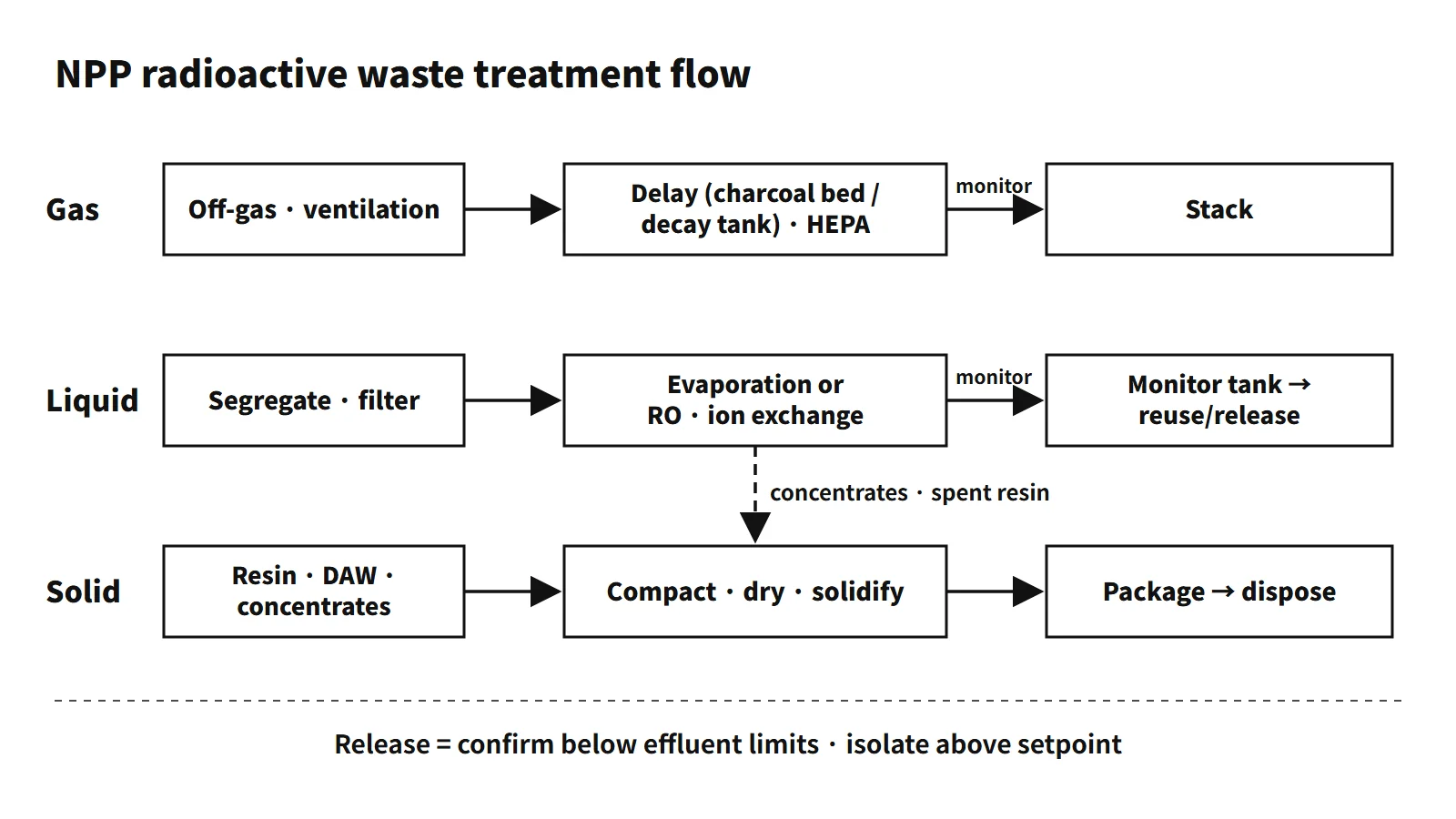
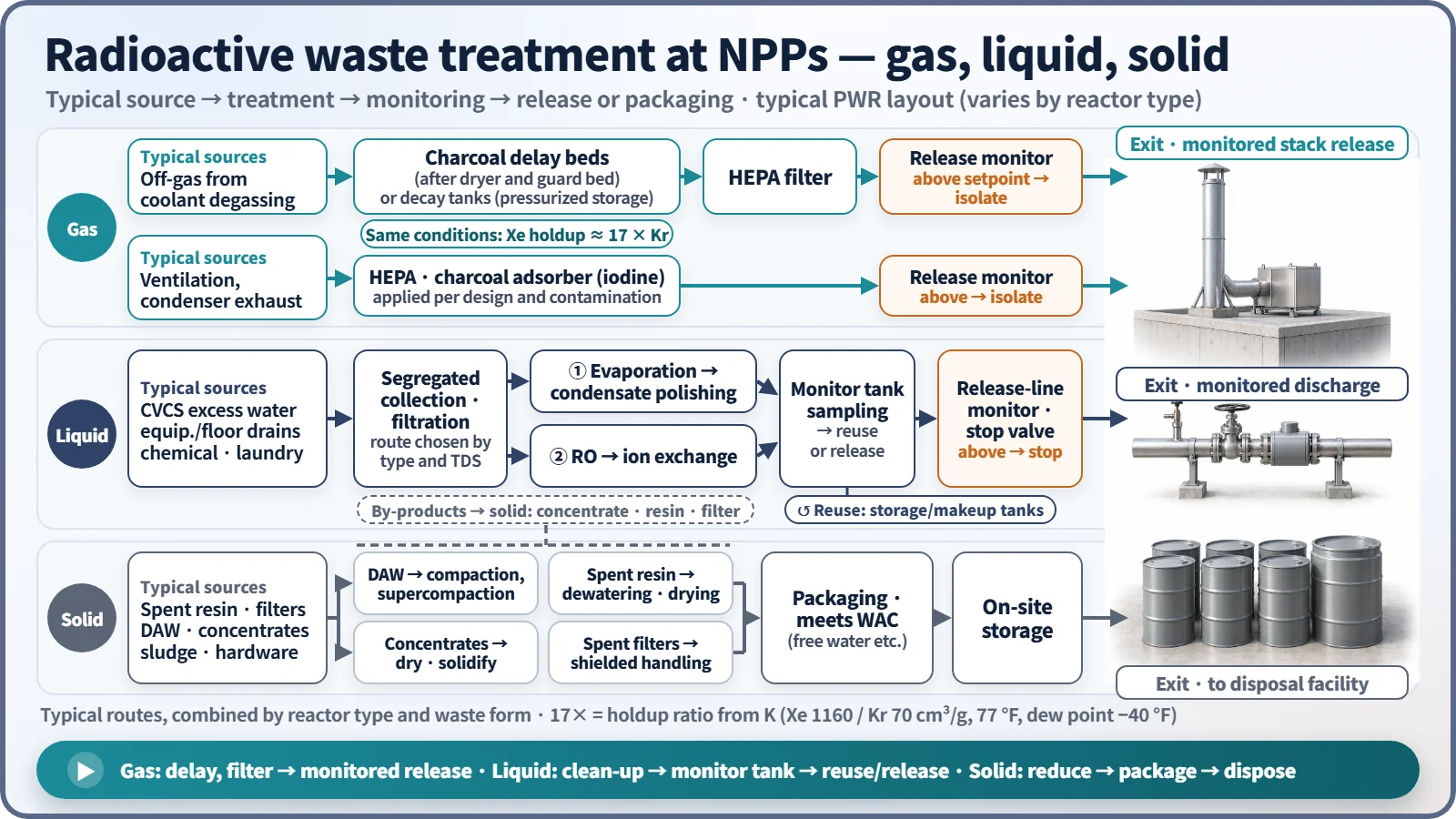
Gas. There are two routes. High-activity gas stripped from the primary coolant goes to the gaseous waste management system. Building ventilation and condenser exhaust take a separate route: they are filtered by HEPA filters and charcoal adsorbers (for iodine) and released under monitoring. The gaseous waste system works in one of two ways. In the decay-tank method the gas is held in pressurized storage tanks for some tens of days. In the charcoal delay-bed method the gas passes through a dryer and guard bed and then through charcoal at room temperature, and Kr and Xe decay during the time they are held back by adsorption (adopted in the APR1400).
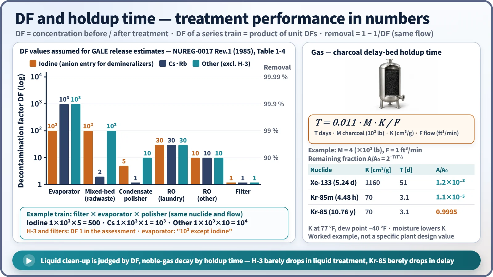
T = 0.011 · M · K / F (days)
Here M is the charcoal mass (thousand lb), K the dynamic adsorption coefficient (cm³/g) and F the flow rate (ft³/min). In the same charcoal bed under the same conditions (77 °F, dew point −40 °F), Xe (K 1160) stays about 17 times longer than Kr (K 70). In a decay tank Xe and Kr are stored for the same time. After the delay, the gas passes through a HEPA filter and the release-line monitor to the stack. If the monitor exceeds its setpoint, the isolation valve on that release line closes automatically. Hydrogen is kept below the flammable range by nitrogen dilution and O₂/H₂ analyzers.
Liquid. Segregated collection by waste type is the starting point. There are two typical routes. ① High-TDS waste is filtered and de-oiled, concentrated in an evaporator, and the condensate is polished by ion exchange. ② Recent designs replace the evaporator with a combination of reverse osmosis (RO) and ion exchange. Low-TDS waste may go straight to ion exchange after filtration. Treated water is sampled in a monitor tank and then reused (condensate storage tank, makeup water tank) or released under monitoring; if it exceeds the criteria, it is treated again. The release line also has a monitor and a stop valve, and the discharge pump stops when the setpoint is exceeded. Separation and concentration do not destroy radioactivity — they move it into concentrates, spent resin and spent filters.
Solid. Each waste type has its own method. DAW is volume-reduced by sorting (screening out uncontaminated items), compaction and then supercompaction. Supercompaction crushes a whole 200 L drum and places it in an overpack drum of about 300 L. Spent resin is held in a tank for decay storage, then dewatered and dried, and either solidified or placed in a high-integrity container. Concentrates are dried or solidified. Spent filters are handled remotely in shielded casks and packaged. Packages must meet the waste acceptance criteria of the disposal facility, including the limit on free water.
Decontamination factor (DF)
The DF is the activity concentration before treatment divided by the concentration after treatment. For the same flow, the removal fraction is 1 − 1/DF, so a DF of 10 means 90 %, 100 means 99 % and 1000 means 99.9 %. For a series train through which the same nuclide passes, the system DF is the product of the unit DFs. The values below are assumptions for the release-estimation code GALE, not equipment performance guarantees.
| Unit (NUREG-0017 Rev.1, Table 1-4) | Halogens (iodine) | Cs, Rb | Other |
|---|---|---|---|
| Evaporator (miscellaneous waste, boric acid recovery) | 10² | 10³ | 10³ |
| Mixed-bed demineralizer (radwaste) | 10² | 2 | 10² |
| Mixed-bed demineralizer (evaporator condensate polishing) | 5 | 1 | 10 |
| Reverse osmosis (laundry / other waste) | 30 / 10 | 30 / 10 | 30 / 10 |
| Filter | 1 | 1 | 1 |
For the example train in the table (filter → evaporator → condensate-polishing demineralizer), the DF is 500 for iodine, 10³ for Cs and 10⁴ for other nuclides. Cs is poorly retained by the demineralizers. Most liquid H-3 is tritiated water (HTO), so it is assigned DF 1 in every unit. A filter DF of 1 means the assessment does not credit any removal of dissolved nuclides.
What it means in a plant
- Design: segregated collection by waste type, and capacity sized for single failures and abnormal waste generation, are the basics. Seismic and quality classes of system structures follow design guides such as US NRC RG 1.143. Leak dikes and tank high-level alarms are also provided.
- Operation: releases are managed in three stages — sampling of the monitor tank before release, continuous monitoring during release, and automatic termination when the setpoint is exceeded. The condenser air-ejector monitor is the first place where SG tube leakage shows up.
- Design examples: OPR1000-family plants use evaporators, demineralizers and charcoal delay beds. The APR1400 uses RO with ion exchange and charcoal delay beds.
- Vitrification: some plants vitrify combustible DAW and low-level spent resin in a cold crucible induction melter (CCIM).
Regulatory and design criteria
- Effluent limits: national regulations set concentration limits for radionuclides in gaseous and liquid effluents, judged as averages over a set period. Release-line monitors and the pre-release sampling of monitor tanks exist to demonstrate compliance with them.
- Design dose objectives: separate from the concentration limits, plant design is checked against annual dose objectives for the public. For example, in the United States 10 CFR 50 Appendix I sets per-unit design objectives of 3 mrem (0.03 mSv) whole-body dose from liquid effluents, 10 mrad (0.1 mGy) gamma and 20 mrad (0.2 mGy) beta air dose from noble gases, and 15 mrem (0.15 mSv) organ dose from radioiodine and particulates.
- ODCM (Offsite Dose Calculation Manual): the document that sets the equations for release-monitor alarm and trip setpoints and the method for calculating public doses. It is paired with the effluent limits in the technical specifications (US basis: NRC GL 79-03).
- Design guides: for example, US NRC RG 1.143 sets the seismic and quality classes of radwaste systems, and RG 1.140 covers normal ventilation filters and adsorbers.
Easily confused pairs
| Topic | A | B |
|---|---|---|
| Gas delay | Decay tank: pressurized storage, batch, delay by storage time | Charcoal delay bed: continuous flow, delay by adsorption, sensitive to moisture |
| Liquid concentration | Evaporation: copes with high TDS, DF 10³, consumes energy and produces concentrates | Ion exchange and RO: low TDS, produce spent resin and RO concentrate, low Cs DF |
| Criteria | Effluent limits: release concentrations, averaged over a set period | Design dose objectives: annual public dose (e.g. 10 CFR 50 Appendix I) |
| Volume reduction | Compaction: reduces volume only, concentration rises | Clearance: release from regulatory control |
Key points at a glance
- Nuclide formation: fission products (Kr, Xe, I, Cs), activated corrosion products (Co-58, Co-60), activated coolant (H-3, C-14, N-16).
- Gas: stripped coolant off-gas → decay tanks or charcoal delay beds (T = 0.011MK/F) → HEPA → monitored release; building ventilation → HEPA and charcoal adsorbers → monitored release; isolation above the setpoint.
- Liquid: collect CVCS excess water, equipment and floor drains, chemical and laundry wastes separately → evaporation (DF 10³) or RO → ion exchange → monitor tank → reuse or monitored release.
- Solid: compaction and supercompaction of DAW, dewatering and drying of spent resin, drying or solidification of concentrates, shielded packaging of spent filters → meet acceptance criteria → repository.
- DF: ratio of concentrations before and after treatment; multiplies in series; H-3 has DF 1 (and Kr-85 barely decreases with delay).
- Criteria: concentration-based effluent limits, annual design dose objectives (e.g. 10 CFR 50 Appendix I, liquid 3 mrem = 0.03 mSv), and the ODCM that links release-monitor setpoints to public dose.