Thermal Hydraulics & Thermodynamics · C-TH-005
Rankine Cycle and Thermal Efficiency — The PWR Secondary T-s Diagram, with Reheat and Regeneration
Why a saturated-steam PWR cycle reaches about 38 % ideal and 33–35 % actual efficiency, and why regeneration raises efficiency while the MSR controls moisture.
The Rankine cycle is a steam power cycle in which water repeatedly undergoes adiabatic compression in a pump → constant-pressure heating and evaporation in the steam generator → adiabatic expansion in the turbine → constant-pressure condensation in the condenser; its thermal efficiency is η = Wnet/Qin = 1 − Qout/Qin.
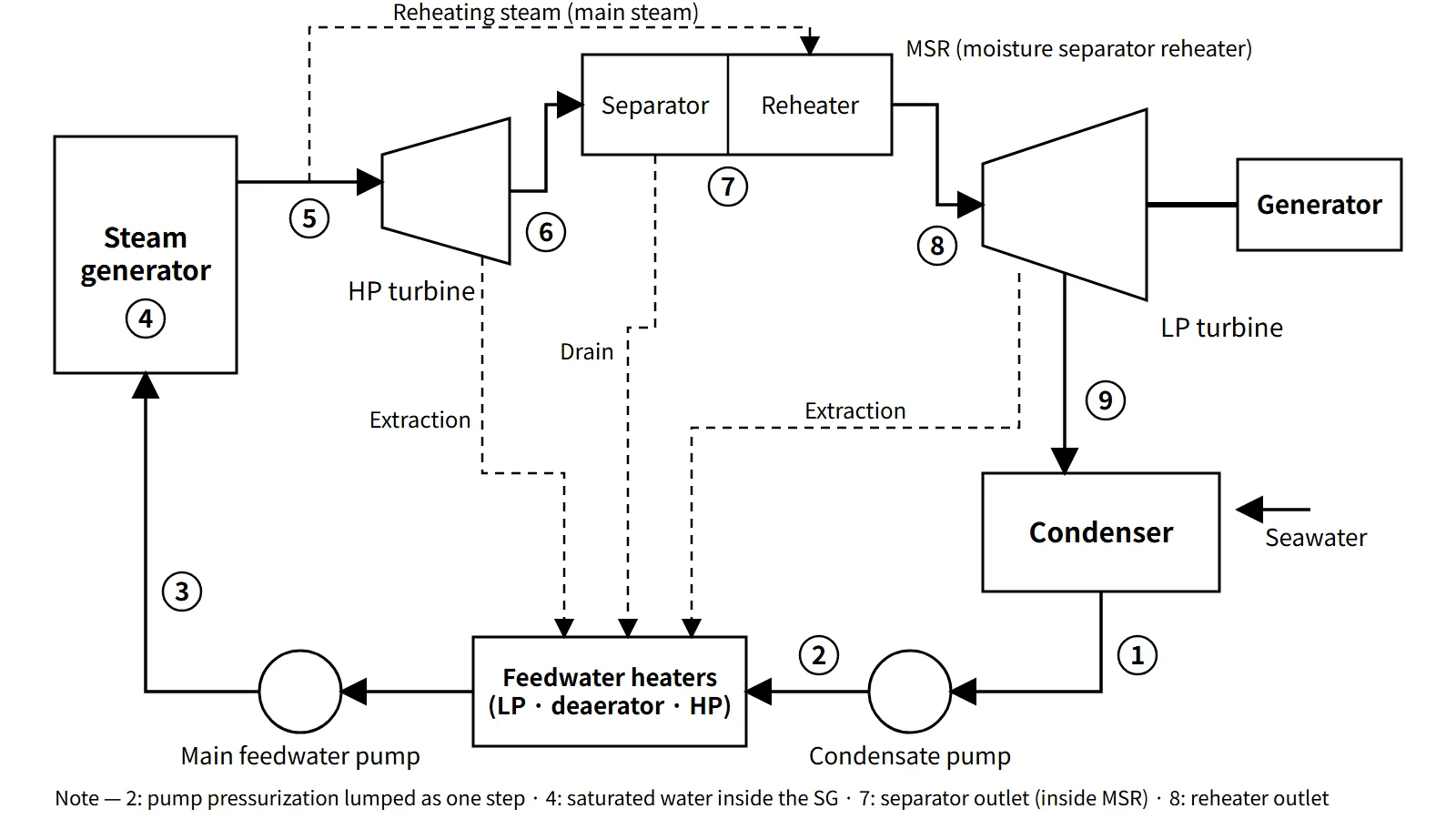
The secondary side of a nuclear plant (the power conversion system) runs a regenerative-reheat Rankine cycle, adding reheat (the moisture separator reheater, MSR) and regeneration (feedwater heaters).
Principle and mechanism
The four processes and the efficiency equation
State numbers for the basic cycle: ① condenser outlet, ② pump outlet, ③ boiler outlet, ④ turbine outlet.
| Process | Component | Ideal process | Energy |
|---|---|---|---|
| ①→② | Feedwater pump | Isentropic compression (compressed liquid) | wp = h2 − h1 ≈ v1(PH − PL) |
| ②→③ | Steam generator | Constant-pressure heating → evaporation | qin = h3 − h2 |
| ③→④ | Turbine | Isentropic expansion (into wet steam) | wt = h3 − h4 |
| ④→① | Condenser | Constant-pressure, constant-temperature condensation | qout = h4 − h1 |
- η = [(h3 − h4) − (h2 − h1)] / (h3 − h2)
- Unlike the Carnot cycle, the steam is fully condensed before the liquid is compressed, so the pump work is less than 1 % of the turbine work. The price is a low-temperature heat-addition segment where cold feedwater is warmed.
- Efficiencies are compared most cleanly with the mean heat-addition temperature T̄H = qin/Δs. Then η = 1 − TL/T̄H, and every efficiency improvement can be explained as "raising T̄H or lowering TL".
PWR secondary numbers (IAPWS-IF97 calculation)
Example conditions: saturated steam at 6.9 MPa at the steam generator outlet (284.9 °C), condenser at 5 kPa (32.9 °C), isentropic pump and turbine.
- h3 = 2,773.9, h4 = 1,773.7 (x4 = 0.675), h1 = 137.8, h2 = 144.7 kJ/kg
- wt = 1,000.2, wp = 6.9, qin = 2,629.2 kJ/kg → η = 37.8 %
- Carnot efficiency between the same temperatures 45.2 %; mean heat-addition temperature 218.7 °C
Because of the primary coolant temperature (around 300 °C), a PWR has low steam conditions and a lower efficiency than a fossil plant (for example 24 MPa and 538 °C, ideal efficiency about 44.7 %). The bigger problem is that the turbine exhaust moisture of the basic cycle exceeds 32 %, which is why an MSR is needed.
Three ways to raise efficiency, and what is special in a nuclear plant
| Method | Principle on the T-s diagram | Application on the PWR secondary side |
|---|---|---|
| Superheating | Heat the steam above saturation → T̄H↑, exhaust quality↑ | U-tube steam generators deliver saturated steam; once-through SGs (OTSG) give slight superheat |
| Reheating | Reheat partway through expansion → exhaust quality↑; T̄H↑ if the reheat temperature is high | MSR: removes moisture from the HP turbine exhaust and reheats with main steam. The reheat temperature cannot exceed the main-steam saturation temperature, so the efficiency gain is small and the main purpose is moisture control |
| Regeneration | Preheat feedwater with turbine extraction steam → removes the low-temperature heat-addition segment → T̄H↑ | LP and HP feedwater heaters and a deaerator; typically 6–7 stages in large PWRs |
Comparing with a calculation model (HP extraction at 2.8 MPa, moisture separation at 1.0 MPa then reheat to 260 °C, LP extraction at 0.15 MPa, final feedwater 230.9 °C):
- Basic 37.8 % → 3-stage regeneration 42.6 % → regeneration + MSR 42.5 % (exhaust quality 0.675 → 0.820, moisture 32.5 % → 18.0 %)
- Under these conditions regeneration provides the efficiency and the MSR handles the moisture. The efficiency effect of the MSR depends on the reheat conditions and actual turbine losses, so it should not be generalized.
- With an 85 % turbine internal efficiency, regeneration + MSR gives 36.8 %; adding moisture losses, generator losses and house load, the actual net efficiency is about 33–35 % (example APR1400: 3,983 MWt → net about 1,400 MWe, about 35 %).
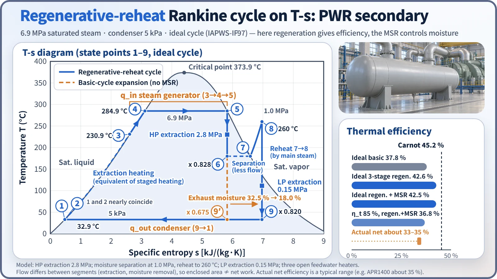
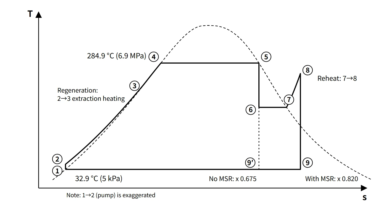
State points on the T-s diagram (regenerative-reheat cycle)
| No. | Location / component | State | What happens |
|---|---|---|---|
| 1 | Condenser outlet | Saturated water at 5 kPa, 32.9 °C | Condensation complete |
| 1→2 | Condensate and main feedwater pumps | Compressed liquid | Pressure rise; almost coincides with 1 on T-s |
| 2→3 | LP and HP feedwater heaters, deaerator | 33 → 230.9 °C | Feedwater preheated by extraction steam (regeneration) |
| 3→4 | SG preheating region | 6.9 MPa compressed liquid → saturated liquid | Sensible heating |
| 4→5 | SG boiling region | Isothermal at 284.9 °C | Evaporation; saturated steam at the outlet |
| 5→6 | HP turbine | 1.0 MPa, x = 0.828 | Expansion; extraction at 2.8 MPa |
| 6→7 | Moisture separator | Saturated steam at 1.0 MPa | Moisture removal (drains to the feedwater system, so flow decreases) |
| 7→8 | Reheater | Superheated to 260 °C | Reheated by main steam (5) |
| 8→9 | LP turbine | 5 kPa, x = 0.820 | Expansion; LP extraction |
| 9→1 | Condenser | Constant pressure and temperature | Condensation; heat rejected to seawater |
Because extraction and moisture separation change the flow rate from segment to segment, the enclosed area of this diagram must not be read directly as net work. Likewise, 2→3 is drawn as one line, although in reality it is a series of pressure rises and mixing heaters, stage by stage.
What it means in a plant
Design — efficiency and moisture
- Secondary steam conditions are set by the primary hot-leg temperature and the steam generator heat-transfer temperature difference. The same reason explains why steam pressure falls after a power uprate.
- Because expansion takes place in the wet-steam region, moisture erosion and moisture loss in the last LP turbine stages are design variables. The Baumann rule of thumb is used: about 1 % loss of stage efficiency per 1 % moisture.
- Wet-steam and hot-water piping is vulnerable to flow-accelerated corrosion (FAC).
Operation — condenser vacuum and seawater temperature
Condenser pressure is set by the cooling seawater temperature. For a site with seawater 6–7 °C warmer (for example, in the Middle East), the ideal basic cycle (assuming the condensing temperature rises by the same amount) goes from 5 kPa (32.9 °C) to 7.4 kPa (40.0 °C), and efficiency falls from 37.8 to 36.8 %, about 1 percentage point. If the primary capacity and the main steam and feedwater piping are fixed, the electrical output falls. Compensating requires a larger condenser heat-transfer area and circulating-water flow, and LP turbine last stages suited to the higher back pressure.
Worked example: secondary efficiency from a heat balance
Data: primary flow 18,640 kg/s, primary inlet/outlet 295/315 °C, specific heat 6.1 kJ/kg℃; condenser cooling water 28,230 kg/s, 17/31 °C, specific heat 4.3 kJ/kg℃.
- Qin = 18,640 × 6.1 × (315 − 295) = 2,274,080 kW ≈ 2,274 MWt (total heat available to the secondary side)
- Qout = 28,230 × 4.3 × (31 − 17) = 1,699,446 kW ≈ 1,699 MW
- η = 1 − 1,699.4/2,274.1 = 25.3 % (net work about 575 MW)
Regulatory and design criteria
The thermodynamic cycle itself is not a safety-regulation item; it connects to the review criteria for secondary-side equipment (for example, those of the US NRC) and to international industry standards.
| Basis | Key point |
|---|---|
| NUREG-0800 SRP Chapter 10, "Steam and Power Conversion System" | Review of 10.2 turbine generator, 10.3 main steam, 10.4.1 main condenser, 10.4.7 condensate and feedwater systems |
| 10 CFR 50 App. A, GDC 4 | Protection against dynamic effects such as turbine missiles |
| NRC GL 89-08 (1989) | Management of secondary piping wall thinning (FAC) — prompted by the Surry Unit 2 (1986) feedwater pipe rupture |
| IAPWS-IF97 | Industrial standard for steam properties (1997, replacing IFC-67) |
| ASME PTC 6 | Steam turbine performance testing |
Differences between older textbook steam tables (based on IFC-67) and IF97 values are too small to affect the results.
Easily confused pairs
| Rankine | Carnot | Reheat | Regeneration | |
|---|---|---|---|---|
| Essence | Liquid compression; practical cycle | Isothermal heat addition and rejection; theoretical upper limit | Reheating partway through expansion | Feedwater preheating by extraction |
| Efficiency basis | T̄H < TH | TH itself | T̄H↑ (with high-temperature reheat) | Removes low-temperature heat addition |
| Meaning for a PWR | Basic 37.8 % | 45.2 % | Moisture control (MSR) | Main means of raising efficiency |
Also distinguish thermal efficiency from heat rate: HR = 3,600/η kJ/kWh, so η = 35 % gives about 10,286 kJ/kWh.
Key points at a glance
- Definition: steam power cycle of pump compression → constant-pressure heating in the SG → isentropic expansion in the turbine → constant-pressure condensation in the condenser.
- Efficiency: η = (wt − wp)/qin = 1 − qout/qin, with wp ≈ v(PH − PL).
- Mean heat-addition temperature: η = 1 − TL/T̄H; improvements raise T̄H or lower TL.
- PWR example: 6.9 MPa saturated steam, 5 kPa → ideal 37.8 %, Carnot 45.2 %, actual net about 33–35 %.
- Superheat: T̄H↑; PWR U-tube SGs deliver saturated steam.
- Reheat (MSR): exhaust quality 0.675 → 0.820; main purpose is reducing moisture erosion and loss.
- Regeneration: feedwater preheating by extraction; ideal 37.8 → 42.6 %; 6–7 stages.
- Condenser: warmer seawater → higher back pressure → lower efficiency (about 1 percentage point from 5 to 7.4 kPa); condenser heat QL = Pout(1/η − 1) = ṁ(h4 − h1).