Systems & Equipment · C-SY-008
Emergency Core Cooling System (ECCS) — Passive SITs and Active HPSI and LPSI Sharing Core Cooling Over Time
How passive tanks and active pumps share core cooling by pressure and time after a LOCA, and why hot-leg injection is added hours later.
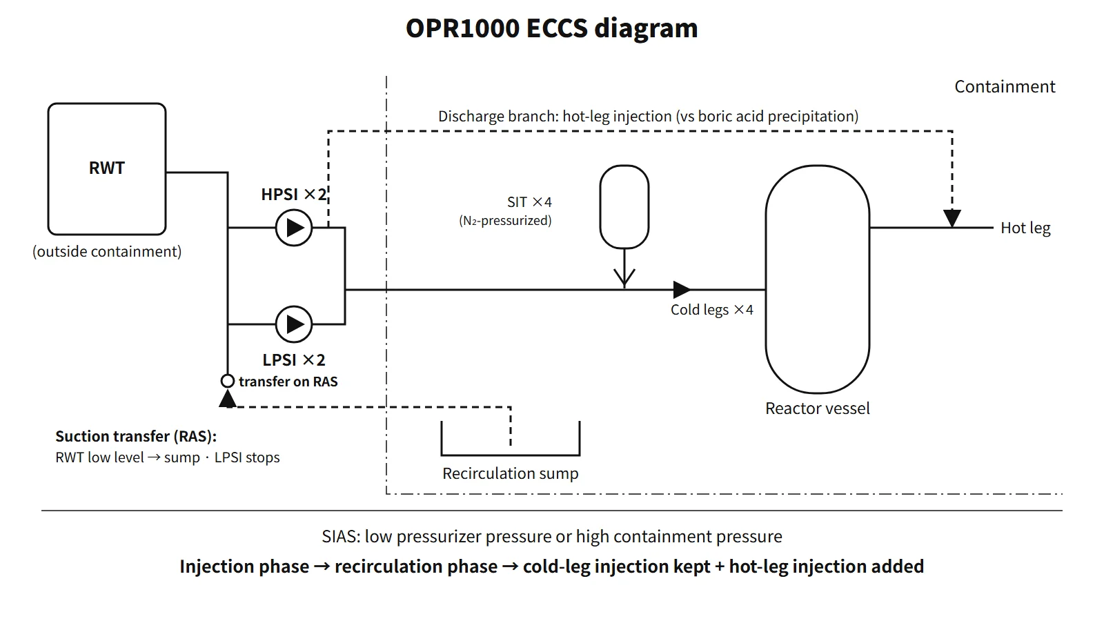
The emergency core cooling system (ECCS) is the engineered safety feature that, in design-basis accidents such as a loss-of-coolant accident (LOCA), injects borated water into the reactor coolant system (RCS) to cool the core and add negative reactivity, and then removes decay heat over the long term by recirculation after the accident. In a pressurized water reactor, the passive safety injection tanks (SITs), the active high- and low-pressure safety injection pumps (HPSI, LPSI), the water sources (refuelling water tank and sump) and the actuation signals (SIAS, RAS) are treated together as one system.
Principle and mechanism
Functions — not a LOCA-only system
- Inventory makeup and core cooling: replaces the coolant lost in a LOCA to recover the core and lower cladding temperature.
- Negative reactivity: highly borated water in the tanks prevents return to criticality in overcooling accidents such as a main steam line break and secures shutdown margin. The negative-reactivity requirement is set mainly by loss of secondary coolant.
- Long-term cooling: when the water source runs out, recirculation from the containment sump keeps removing decay heat.
- Prevention of boric acid precipitation: during long-term cooling, simultaneous hot-leg and cold-leg injection flushes out boric acid concentrating in the core.
Technical specification bases list the accidents covered as LOCA, control element assembly ejection, loss of secondary coolant and steam generator tube rupture (SGTR).
OPR1000 configuration — passive and active parts
| Component | Number and arrangement (OPR1000) | Function |
|---|---|---|
| Safety injection tank (SIT) | 4, one per cold leg, nitrogen-pressurized | Injects automatically by pressure difference when RCS pressure falls below tank pressure (passive). Isolation MOV open during operation with power removed |
| High-pressure safety injection pump (HPSI) | 2, high head, moderate flow | Small-LOCA makeup, sump recirculation after RAS, hot-leg injection |
| Low-pressure safety injection pump (LPSI) | 2, low head, high flow | High-flow injection in a large LOCA, automatic stop on RAS, also used for shutdown cooling |
| Refuelling water tank (RWT) | Outside containment, sized for a minimum injection period with all ESF pumps running | Water source for the injection phase |
| Recirculation sump | Lowest point of containment, with screens | Water source for the recirculation phase |
| Trisodium phosphate (TSP) | Baskets on the containment floor | Raises the pH of the recirculation water → limits iodine volatility and stress corrosion cracking |
One of the four SITs is assumed to spill straight out of the break. The nitrogen volume, water volume and line sizes are set so that the remaining three do the job.
Actuation signals
- SIAS (safety injection actuation signal): low pressurizer pressure or high containment pressure. The HPSI and LPSI pumps start automatically and the injection header isolation valves open. After an automatic start, the pumps are designed not to be stopped by overcurrent relays or the normal stop switch, to prevent an inadvertent stop.
- RAS (recirculation actuation signal): low RWT level. The LPSI pumps stop automatically and the sump isolation valves open automatically. The operator closes the RWT outlet valves. From then on the HPSI and containment spray pumps take water from the sump.
Roles split by pressure
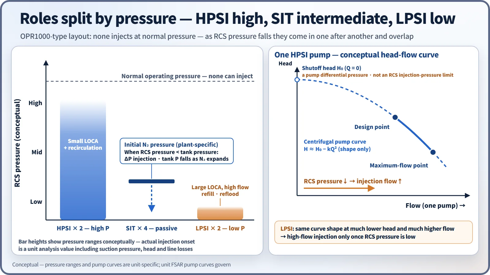
The three means cover different pressure ranges. HPSI injects even at high pressure and handles small LOCAs; the SITs inject large volumes by pressure difference once the RCS falls below their initial nitrogen pressure; LPSI delivers high flow at low pressure. In a large LOCA all three overlap. Because they are centrifugal pumps, injection flow increases as RCS pressure falls. Each pump has a shutoff head (the head at zero flow). It is a pump differential pressure, so it must not be read directly as the upper RCS absolute pressure for injection; actual values follow each unit's FSAR pump curves. The HPSI shutoff head is chosen so that it can still inject in a small LOCA even if RCS pressure rises to the steam generator relief valve setpoint, so that decay heat can be removed through the steam generators.
The order in which the ECCS works in a large LOCA
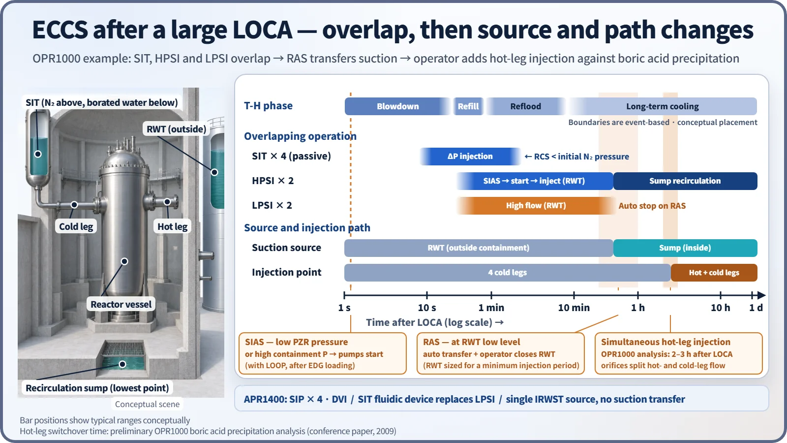
- Rapid depressurization → reactor trip and SIAS (within seconds)
- During blowdown the RCS falls below SIT nitrogen pressure → SIT injection, supporting refill (as it discharges the nitrogen expands and tank pressure also falls)
- HPSI and LPSI inject RWT water into the four cold legs (with loss of offsite power assumed, after the emergency diesel generators start and pick up load)
- Reflood → core quench
- RWT reaches low level → RAS → sump recirculation (HPSI continues, LPSI stops). The RWT capacity criterion is a minimum injection period with all ESF pumps at design flow; it is not the RAS time itself
- The operator realigns HPSI discharge for simultaneous hot-leg and cold-leg injection (one OPR1000 analysis example: 2–3 hours after the accident)
- Long-term cooling → transfer to shutdown cooling
Why simultaneous hot-leg injection (hot-leg recirculation)?
With a cold-leg break, water injected into the cold legs boils in the core and leaves as steam. Boric acid does not evaporate, so it accumulates in the core and lower plenum. If the concentration exceeds the solubility limit, boric acid precipitates, blocking flow paths and degrading heat transfer, which threatens the long-term cooling criterion. Injecting into the hot legs as well creates a net flow through the core that flushes the concentrated water out of the break. With a hot-leg break, cold-leg injection alone flushes the core, but because the break location cannot be known in advance, both are injected at the same time. In the OPR1000 the operator opens the hot-leg injection isolation valves on the HPSI discharge (normally closed, no automatic function), and orifices split the flow between the hot and cold legs.
The switchover time is an analysis result. A preliminary OPR1000 boric acid concentration analysis (2009 conference paper) found 2–3 hours and reported that crediting only half of the lower-plenum mixing volume would require an earlier switch. Some US units use 5.5–6 hours.
What it means in a plant
OPR1000 and APR1400
| Item | OPR1000 | APR1400 |
|---|---|---|
| Active injection | 2 HPSI + 2 LPSI (two mechanical trains) | 4 SIPs (four mechanical trains, two electrical divisions) |
| Injection point | Cold legs | Direct vessel injection (DVI) |
| Low-pressure high flow | LPSI | SIT fluidic device (automatic switch from high to low flow) |
| Water source | RWT (outside) → sump (RAS) | IRWST (inside), single source, no RAS |
| Hot-side injection | HPSI hot-leg injection | Simultaneous hot-side injection (about 3 hours in the US DC analysis) |
Surveillance during operation
Under CE-type standard technical specifications, all four SITs and both ECCS trains must be operable during power operation and at hot conditions above specified pressurizer pressures. An inoperable train has a limited allowed outage time, and SIT level, pressure and boron concentration are surveilled at fixed intervals.
Regulatory and design criteria
For example, in the United States:
| Basis | Key point |
|---|---|
| 10 CFR 50.46, Appendix K | Acceptance criteria (peak cladding temperature, cladding oxidation, hydrogen generation, coolable geometry, long-term cooling) and conservative evaluation models |
| 10 CFR 50 Appendix A, GDC 35, 36 and 37 | ECCS function (with a single failure and with onsite or offsite power alone), inspection, testing |
| GDC 2, 4, 5, 17 and 27 | Natural phenomena, dynamic effects, limits on sharing between units, electric power, combined reactivity control |
A single failure means "a postulated single failure plus the failures resulting from it", and in ECCS analysis the loss of one emergency diesel generator (loss of one train) is the typical worst single failure. In the United States, 50.46c was withdrawn in 2024, and the current 50.46(b) applies.
Easily confused pairs
| ECCS | Decay heat removal (shutdown cooling) system | |
|---|---|---|
| Situation | Accidents (LOCA, MSLB, etc.) | Normal cooldown and shutdown |
| Pressure | High to low, during the accident | Low (entered only after cooldown and depressurization) |
| Equipment | SITs, HPSI, LPSI | Shutdown cooling pumps (in the OPR1000 the LPSI pumps double as these) |
| Injection phase | Recirculation phase | |
|---|---|---|
| Water source | RWT | Containment sump |
| Pumps running | HPSI, LPSI | HPSI (+ spray pumps) |
| Transition | Starts on SIAS | RAS (low RWT level) |
Key points at a glance
- Definition: engineered safety feature that injects borated water into the RCS in a LOCA and similar accidents to provide core cooling, negative reactivity and long-term cooling.
- Functions: (1) inventory makeup and core cooling; (2) boron negative reactivity (MSLB); (3) long-term cooling by recirculation; (4) prevention of boric acid precipitation by simultaneous hot-leg injection.
- Passive part: four SITs (nitrogen-pressurized, cold legs, one assumed lost).
- Active part: two HPSI (high pressure, small LOCA, recirculation), two LPSI (low-pressure high flow, stop on RAS).
- Water sources: RWT (outside containment) → RAS → sump (TSP raises pH).
- Signal: SIAS = low pressurizer pressure or high containment pressure.
- Design basis: 10 CFR 50.46 acceptance criteria; GDC 35–37 (single failure, onsite or offsite power alone, inspection and testing).
- APR1400: four SIPs, DVI, SIT fluidic device (no LPSI), IRWST (no RAS).