Systems & Equipment · C-SY-004
Diverse Protection System (DPS) — An Independent Trip Path Against Common-Cause Failure of the Protection System
Why a digital protection system needs a second, different trip path, and how the DPS trips the reactor, the turbine and starts auxiliary feedwater on its own.
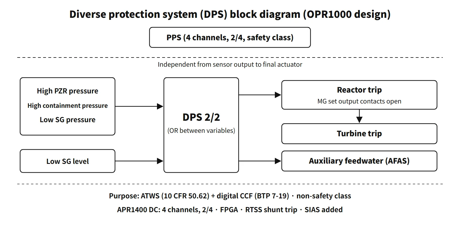
The diverse protection system (DPS) is a non-safety-class backup protection system that is independent of the plant protection system (PPS) from the sensor output to the final actuating devices and is built on a different technology. It trips the reactor, trips the turbine and actuates auxiliary feedwater to cope with ATWS and with software common-cause failure (CCF) of the digital protection system, and in some designs it also generates safety injection and containment isolation signals.
The main regulatory anchors are 10 CFR 50.62 and NUREG-0800 BTP 7-19.
Principle and mechanism
Why add one more system?
The PPS has four channels in a 2-out-of-4 arrangement, so it tolerates single failures well. But all four channels run the same software on the same platform, so a single latent design defect could disable all four at once. That is a common-cause failure. Adding channels (redundancy) cannot prevent it; the defence is to add something different (diversity).
- Independence: signal and actuation paths separate from the PPS, from the sensor output to the actuating device
- Technology diversity: if the PPS uses PLCs, the DPS uses a DCS or FPGAs
- Functional diversity: the same event is also detected through a different variable, such as containment pressure
- Actuator diversity: at standard plants, control-rod power is cut by opening the MG set output contacts instead of the reactor trip breakers
Input → coincidence logic → output (OPR1000 design)
| Output | Input variables | Final action |
|---|---|---|
| Reactor trip | High pressurizer pressure, high containment pressure, low steam generator pressure (added later by design change after a CCF reassessment) | CEDM MG set output contacts open → control rods drop |
| Turbine trip | Follows the DPS reactor trip (signal path is design-specific) | Turbine trips |
| Auxiliary feedwater actuation (DPS-AFAS) | Low steam generator level | Auxiliary feedwater pumps and valves start |
Each variable uses channel coincidence (2/2), and the variables are combined by OR. The reactor does not need high pressurizer pressure and high containment pressure together to trip.
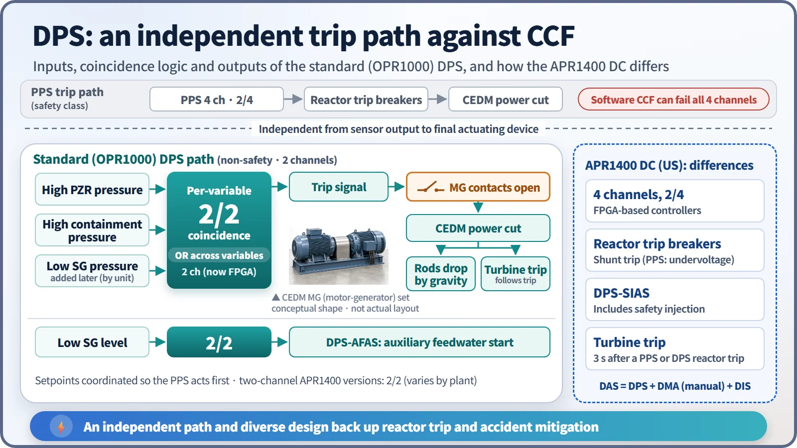
The setpoints are coordinated so that the PPS acts first. There is no interlock between the DPS and the PPS, so if the setpoint margin is small, the DPS could trip the reactor before the PPS. The DPS acts on its own conditions but is set to follow the PPS in normal circumstances. For APR1400 high pressurizer pressure this margin was smaller than the total DPS channel uncertainty, so the setpoint method was refined.
What it means in a plant
Output signals in the OPR1000 design and their purpose
In the OPR1000 design the DPS outputs are as follows.
- Reactor trip signal: two channels in 2/2 logic cut power to the CEDMs by opening the CEDM motor-generator (MG) set output contacts. This is a different actuating device from the PPS reactor trip breakers. The DPS manual trip button in the main control room opens the same contacts. The purpose is to shut off core power during ATWS.
- Turbine trip signal: stops steam extraction on the secondary side to preserve steam generator inventory.
- Auxiliary feedwater actuation signal: starts auxiliary feedwater on low steam generator level to secure a heat sink.
- Status and alarm signals go to the annunciator system and the plant computer.
The hardware has two channels and dual power supplies. The controllers were originally PLCs and have since been replaced with FPGAs (FLC). The 2/2 logic prevents spurious trips and spurious AFAS but cannot tolerate a fault: bypassing one channel for testing or maintenance removes the function.
Why a low-SG-pressure trip was added
A CCF assessment has to reflect the reload core, the power increase from the post-accident decrease in xenon and the change in axial power distribution. When a reassessment of plants with digital protection systems included these effects, it showed that for a main steam line break outside containment combined with CCF, fuel could reach its melting temperature before the DPS actuated automatically.
So pressure transmitters were added on the steam generators and a low steam generator pressure reactor trip was added to the DPS. The transmitters are non-safety class, while their sensing lines and isolation valves are safety class.
How the APR1400 DPS evolved
| Item | Earlier two-channel APR1400 versions | APR1400 DC (US) |
|---|---|---|
| Channels and logic | 2 channels, 2/2 | 4 channels, 2/4 |
| Platform | DCS | FPGA-based controllers |
| Added functions | Later versions: conventional switches and a test panel in each cabinet, then SIAS and DPS and DMA signals to the containment isolation valves | SIAS; shunt trip of the RTSS breakers (the PPS uses the undervoltage trip) |
DPS-SIAS was added in designs whose CCF assessment does not credit manual action within 30 minutes after an accident. The basis was an analysis showing that if a large LOCA coincides with CCF of the PPS and ESF-CCS, fuel damage is a concern about 5 minutes after the safety injection tanks finish discharging (conference paper, 2012). In those designs the containment isolation valves also receive a DPS signal (through a safety-class isolator) and a DMA signal (analog hardwired).
In the US-certified APR1400, the DPS turbine trip starts automatically with a 3-second delay on a PPS or DPS reactor trip condition. The DPS, DMA and DIS together are called the diverse actuation system (DAS).
- DMA (diverse manual ESF actuation): switches in the main control room for manual control of key safety functions without passing through the digital safety system
- DIS (diverse indication system): a single-channel system that continuously displays critical safety variables on equipment different from the safety I&C
The DPS is credited for meeting 10 CFR 50.62, and the DAS as a whole for meeting the four points of BTP 7-19.
Relation to ATWS events
The APR1400 ATWS assessment considers six AOOs with reduced heat removal: (1) loss of external load, (2) turbine trip, (3) loss of condenser vacuum, (4) closure of the main steam isolation valves, (5) loss of offsite power, (6) loss of normal feedwater.
Regulatory and design criteria
For example, in the United States:
| Basis | Key point |
|---|---|
| 10 CFR 50.62(c)(1)(2) | Diverse turbine trip and auxiliary feedwater for all PWRs; diverse scram system for CE and B&W plants |
| SRM-SECY-93-087 II.Q → BTP 7-19 | Four D3 points for digital I&C; current Rev. 9 (May 2024) |
The four points of BTP 7-19 are: (1) perform a D3 assessment; (2) analyse each event in the accident analysis with a postulated CCF, using best-estimate methods; (3) if a CCF disables a safety function, provide a different means not affected by the CCF (which may be non-safety); (4) provide independent and diverse displays and manual controls for critical safety functions in the main control room. The analysis is done for each of the four echelons of defense in NUREG/CR-6303 (control, reactor trip, ESFAS, monitoring and indication).
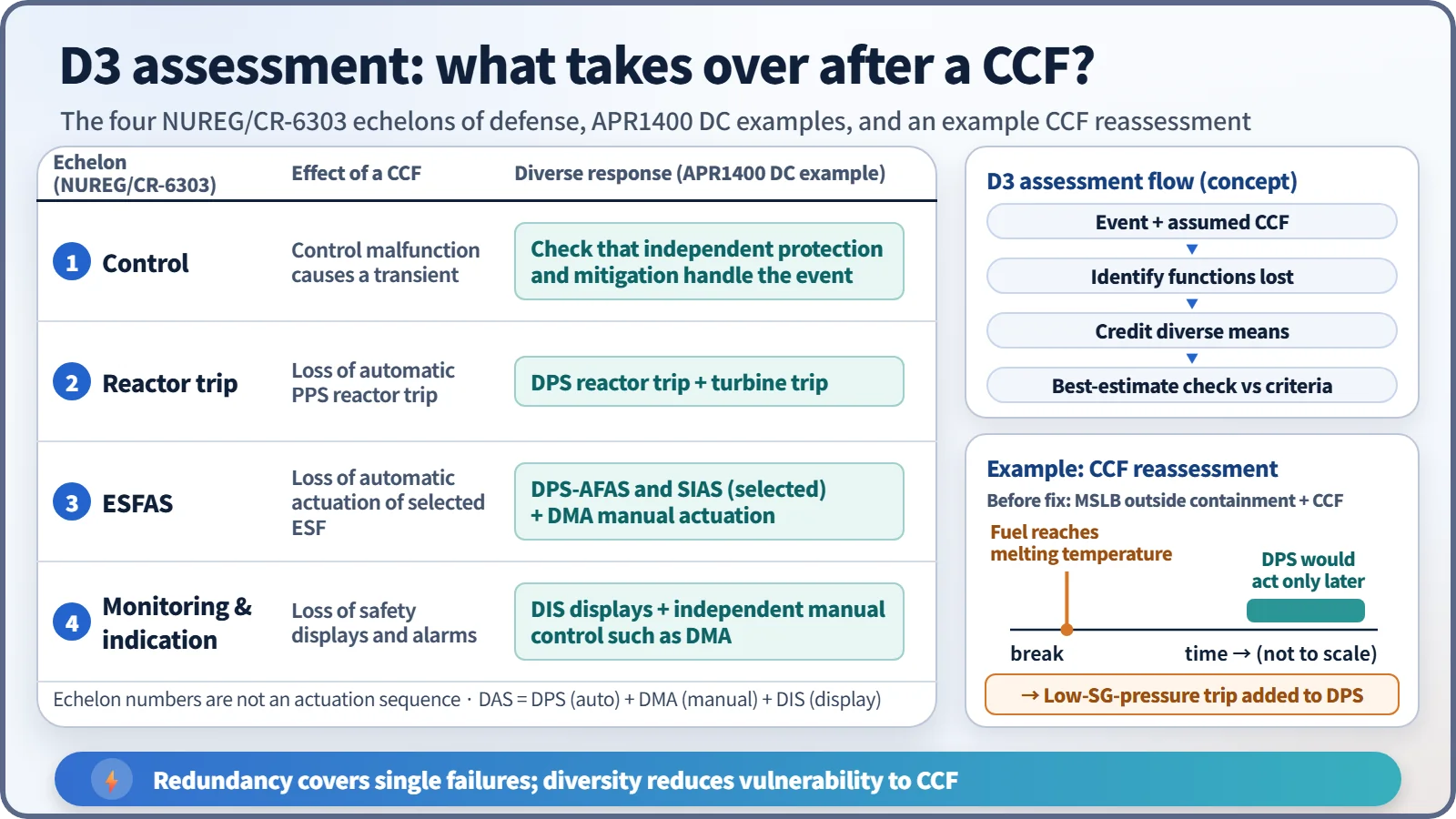
The acceptance criteria are: for an AOO + CCF, dose no more than 10 % of the site dose guideline values and RCPB integrity maintained; for an accident + CCF, dose no more than the guideline values and RCPB and containment integrity maintained.
Easily confused pairs
| PPS | DPS | AMSAC | DSS | |
|---|---|---|---|---|
| Class | Safety | Non-safety | Non-safety | Non-safety |
| Reactor trip | Yes | Yes | No | Yes |
| Turbine trip and auxiliary feedwater | AFAS (an ESFAS function) | Yes | Yes | No |
| Failure covered | Single failure | ATWS and CCF | ATWS | ATWS |
| Applied in | CE plants, APR1400 | OPR1000, APR1400 | Westinghouse plants | CE and B&W plants |
Redundancy installs several identical items to cover single failures; diversity installs something different to reduce vulnerability to CCF.
Key points at a glance
- Definition: non-safety-class backup protection system independent of and diverse from the PPS.
- Purpose: (1) ATWS mitigation (10 CFR 50.62); (2) protection against software CCF of the digital PPS and ESF-CCS (BTP 7-19).
- Reactor trip: high pressurizer pressure, high containment pressure, low SG pressure (added after a CCF reassessment) → CEDM power cut.
- Turbine trip: preserves secondary inventory (APR1400 DC: 3-second delay after a PPS or DPS trip).
- DPS-AFAS: low SG level → auxiliary feedwater starts.
- DPS-SIAS: covers large LOCA + CCF (later APR1400 versions, APR1400 DC).
- Final action: OPR1000 opens the MG set output contacts; the APR1400 DC energizes the shunt trip coils of the RTSS reactor trip breakers (the PPS de-energizes the undervoltage trip coils).
- Configuration: two channels, 2/2 in OPR1000 and earlier APR1400 versions (prevents spurious actuation) → four channels, 2/4 in the DC; platform PLC or DCS → FPGA.
- Setpoints: coordinated so the PPS acts first.
- DAS: DPS (automatic) + DMA (manual) + DIS (indication).