Accidents, Safety Analysis & Severe Accidents · C-SA-013
Severe Accident Features — APR1400 Prevention and Mitigation Features (Depressurization, Hydrogen, Cavity Flooding, Spray Backup)
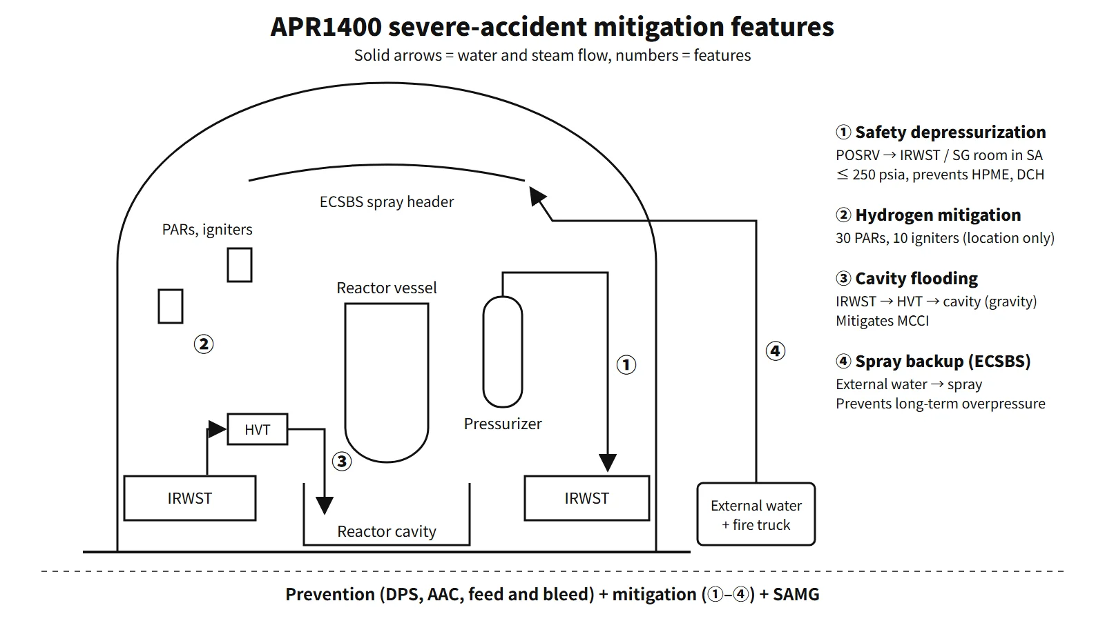
Prevention keeps the core cooled beyond the design basis; mitigation counters each containment threat — HPME and DCH, hydrogen, MCCI and overpressure — with a dedicated feature.
Severe accident features are the combination of prevention features, which stop an event beyond the design basis from progressing to core damage, and mitigation features, which protect containment integrity after the core is damaged and prevent an early or large release of radioactive material. The APR1400 has a dedicated feature for each containment threat.
Principle and mechanism
The line between prevention and mitigation
The dividing line is core damage. Prevention features keep the core cooled even in multiple failures beyond the design basis (ATWS, SBO, total loss of feedwater, etc.). Mitigation features deal one by one with the phenomena that threaten the containment after the core has melted. Mitigation features are commonly grouped by the containment threats they address: combustible gas burn or explosion, high temperature and overpressure, MCCI, HPME, DCH, FCI and containment bypass.
Prevention features — response by scenario (APR1400)
| Scenario that could lead to a severe accident | Prevention feature |
|---|---|
| ATWS (common cause failure of the protection system) | Diverse protection system (DPS): diverse reactor trip on high pressurizer or containment pressure, auxiliary feedwater actuation on low SG level |
| SBO (loss of offsite power + EDGs) | AAC-DG, turbine-driven auxiliary feedwater pump, batteries |
| Total loss of feedwater | Feed and bleed by manually opening the POSRVs, 4 safety injection trains |
| LOCA | 4-train direct vessel injection (DVI), SITs with built-in fluidic devices, IRWST (no switchover to recirculation needed) |
| Interfacing-systems LOCA (ISLOCA) | Higher design pressure of the shutdown cooling system, isolation interlocks of low-pressure systems |
Mitigation features — response by threat
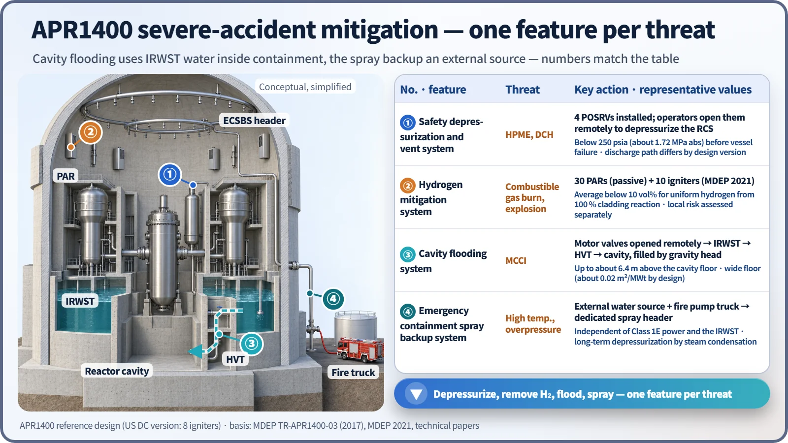
Four systems form the core.
| Feature | Main threat addressed | How it works | Representative values and conditions |
|---|---|---|---|
| Safety depressurization and vent system (SDVS) | HPME, DCH | 4 POSRVs installed, opened remotely by operators | RCS at or below 250 psia (about 1.72 MPa) before vessel failure |
| Hydrogen mitigation system (HMS) | Combustible gas burn or explosion | 30 PARs (passive) + 10 igniters | Average below 10 vol% for uniformly distributed hydrogen from 100 % cladding reaction |
| Cavity flooding system (CFS) | MCCI | Motor-operated valves opened remotely → IRWST → HVT → cavity, filled by gravity head | Flooding up to about 6.4 m above the cavity floor |
| Emergency containment spray backup system (ECSBS) | High temperature and overpressure | External water source + fire pump truck → dedicated spray header | Independent of Class 1E power and the IRWST |
Safety depressurization and vent system — why depressurize before vessel failure?
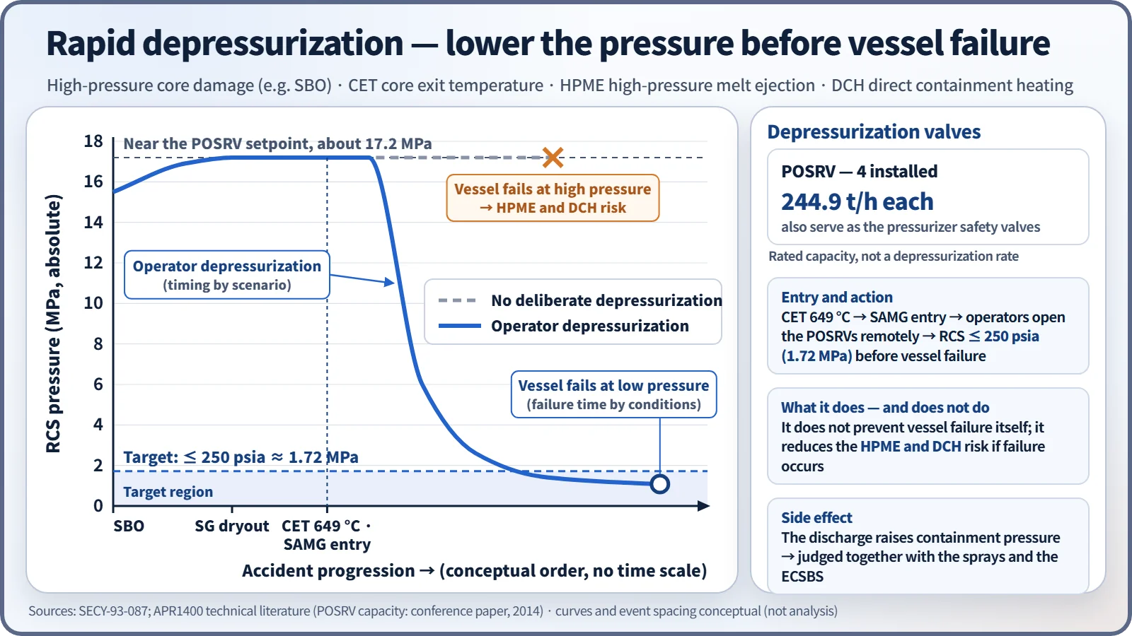
If secondary-side heat removal is lost, as in an SBO, the core melts while the RCS pressure stays near the POSRV opening pressure (about 17 MPa). If the lower head is breached at that point, the melt is ejected at high pressure (HPME), and fine particles rapidly heat and pressurize the containment atmosphere (DCH). So when the core exit temperature reaches 649 °C and the SAMG is entered, operators open the POSRVs to bring the RCS below 250 psia before vessel failure. Depressurization does not prevent vessel failure itself; it reduces the HPME and DCH risk if failure occurs.
Each of the four POSRVs has a rated relief capacity of 244.9 t/h. Design-basis overpressure discharges are condensed in the IRWST spargers, but the literature describes a design in which, during severe-accident depressurization, the discharge is directed toward the steam generator compartment so that hydrogen does not accumulate in the IRWST. Without containment heat removal this discharge raises the containment pressure, so it is judged together with the sprays and the ECSBS.
Hydrogen mitigation system
The PARs handle gradual releases without power, and the igniters burn local high concentrations at low concentration during rapid releases.
Cavity flooding system and cavity geometry
In the CFS, operators open the motor-operated valves between the IRWST and the holdup volume tank (HVT) and between the HVT and the reactor cavity, and IRWST water fills the cavity by the difference in head. There is no pump, but valve operation is needed; the valves are normally closed with power removed. The cavity floods up to about 6.4 m above its floor, cooling the spread melt and scrubbing fission products under water. The cavity has a wide, unobstructed floor (basic design 80.36 m², 0.0201 m²/MWt, meeting the 0.02 m²/MWt value of SECY-93-087) to spread the melt thinly, and a convoluted corium chamber that reduces debris carried up into the upper containment. Uncertainty remains, however, that top flooding alone does not guarantee cooling. A distinctive point of the APR1400 is that the in-containment IRWST serves both for condensing design-basis discharges and as the water source for cavity flooding.
Emergency containment spray backup system
When all design-basis sprays (interchangeable with the shutdown cooling pumps) are lost or the IRWST cannot be used, this system feeds water from an external source such as the raw water tank through an external pump such as a fire pump truck into a dedicated spray header and nozzles. It does not depend on Class 1E power or the IRWST. It condenses steam to prevent long-term overpressure and overtemperature and washes out aerosols. Unlike designs that rely on filtered containment venting (CFVS), the APR1400 secures its containment depressurization function with this system.
Design versions
Some details differ between APR1400 versions; for example, the US Design Certification (DC) version has 30 PARs + 8 igniters and an AC power arrangement of 4 EDG trains + a gas turbine AAC. The European export version EU-APR adopted an ex-vessel core catcher to meet the European Utility Requirements (EUR); the reference APR1400 and the US DC version have no core catcher.
Regulatory and design criteria
US requirements for evolutionary LWRs and the IAEA design requirements are examples of the criteria these features are designed against.
| Basis | Key point |
|---|---|
| For example, US SECY-93-087, 10 CFR 52.47(a)(23) | Severe-accident design of evolutionary LWRs (depressurization, cavity 0.02 m²/MWt, 24 h containment integrity); severe-accident design features in a DC application |
| 10 CFR 50.44(c), IAEA SSR-2/1 Rev.1 Requirement 20 | Hydrogen 10 %; design extension conditions and practical elimination of early or large releases |
Easily confused pairs
| ECSBS | CFVS | CFS | Core catcher | |
|---|---|---|---|---|
| Purpose | Depressurization and scrubbing by spray | Depressurization by filtered venting | Melt cooling by flooding the cavity | Melt captured and cooled in a dedicated structure |
| Release of material | None | Released to the atmosphere after filtering | None | None |
| Where used | APR1400 | Retrofitted at some operating plants after Fukushima | APR1400 | EU-APR, EPR, VVER |
Key points at a glance
- Definition: core-damage prevention features + mitigation features that keep containment integrity and prevent large releases.
- Prevention: ATWS → DPS; SBO → AAC-DG and TDAFW; total loss of feedwater → feed and bleed via POSRVs; LOCA → 4-train DVI, SITs, IRWST; ISLOCA → high design pressure of the shutdown cooling system.
- Safety depressurization and vent: POSRVs (4) opened remotely by operators, at or below 250 psia (1.72 MPa) before vessel failure → prevents HPME and DCH.
- Hydrogen mitigation: 30 PARs + 10 igniters, average below 10 vol%.
- Cavity flooding (CFS): motor valves opened → IRWST → HVT → cavity, filled by gravity head (up to about 6.4 m), wide floor (0.02 m²/MWt concept), corium chamber, MCCI mitigation.
- ECSBS: external water source and fire truck → dedicated spray header, independent of Class 1E power and the IRWST, prevents long-term overpressure.
- Differences: the APR1400 uses ECSBS instead of CFVS; only the EU-APR version has a core catcher.
- Threats addressed: combustible gas, high temperature and overpressure, MCCI, HPME, DCH, FCI, containment bypass.