Operation, Regulation & Quality · C-OP-004
Safety Limits (SL) — Core SL, RCS Pressure SL and Actions When They Are Exceeded
Limits on the process variables that protect the physical barriers, why the core SL follows the SAFDLs and the pressure SL is 110 % of design pressure, and what happens if one is exceeded.
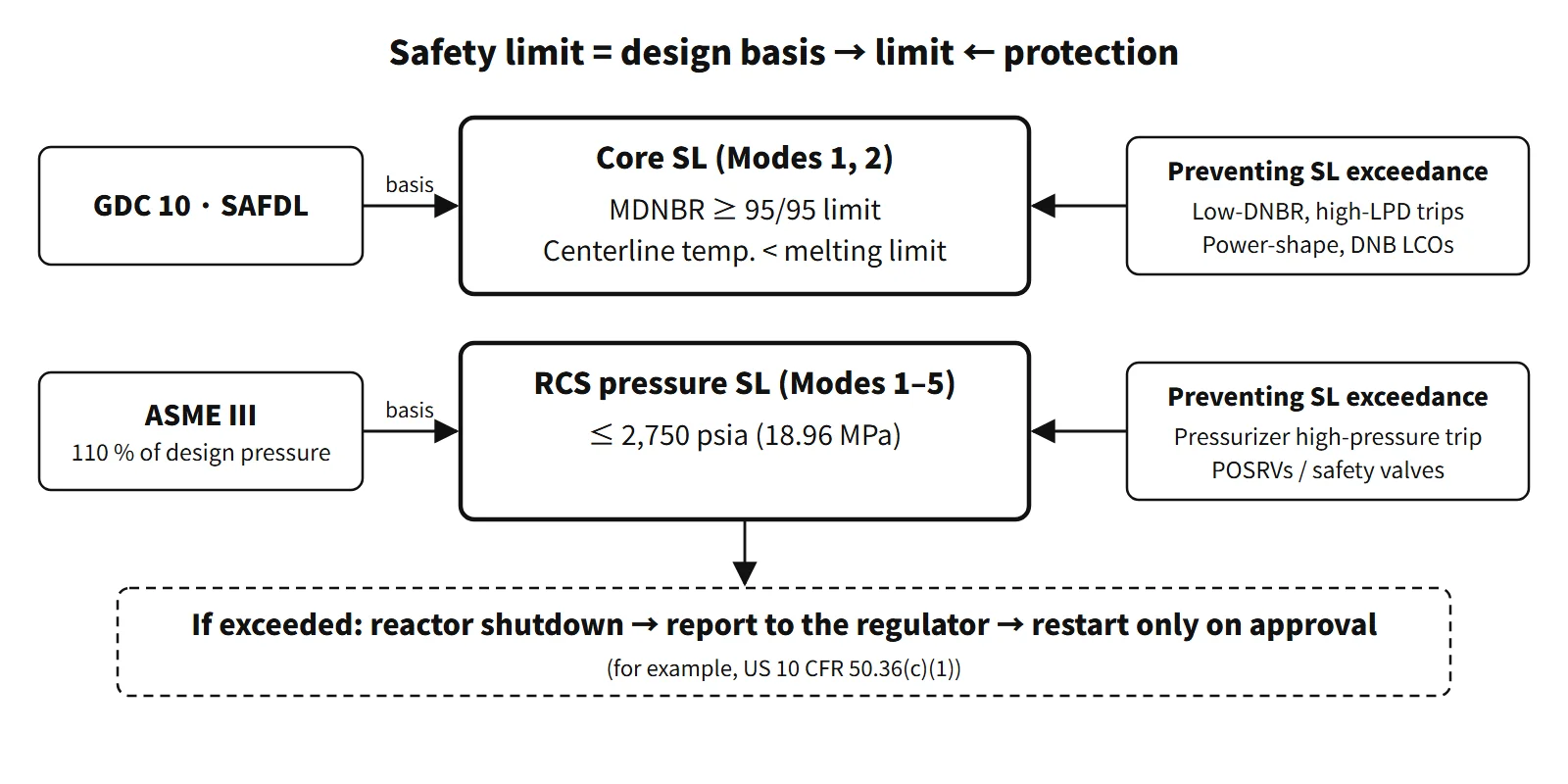
A safety limit (SL) is an operating limit placed on important process variables to protect the integrity of the physical barriers that prevent the release of radioactive material. If it is exceeded, the reactor must be shut down and the event reported to the regulator, and the plant may not restart without approval.
In the United States, for example, the requirement is set in 10 CFR 50.36(c)(1)(i)(A). This entry covers the SL itself.
Principle and mechanism
What it protects — the SL for each barrier
| Item | Barrier protected | Variables | Applicable modes | Standard Technical Specifications clause (example) |
|---|---|---|---|---|
| Core SL | Fuel pellets and cladding | DNBR, peak fuel centerline temperature | 1, 2 | 2.1.1.1 MDNBR ≥ correlation 95/95 limit; 2.1.1.2 centerline temperature < limit |
| RCS pressure SL | Reactor coolant pressure boundary (RCPB) | RCS pressure | 1–5 | 2.1.2 ≤ 2,750 psia |
The core SL applies only in power operation and startup (Modes 1 and 2). The RCS pressure SL applies in Modes 1–5, whenever the reactor vessel head is closed and the system can be pressurized.
The core SL is the SAFDL written as an operating clause
General Design Criterion (GDC) 10 requires that the specified acceptable fuel design limits (SAFDLs) not be exceeded during normal operation and anticipated operational occurrences (AOOs). The two principal SAFDLs become the core SL directly.
- MDNBR ≥ the 95/95 limit of the CHF correlation: it guarantees, at a 95 % confidence level, a 95 % probability that DNB does not occur in the hot rod. The limit differs by correlation and methodology; for example, it is 1.29 for APR1400 (KCE-1). The often-quoted "1.3" dates from the W-3 era; the applicable value is the correlation-specific limit.
- Peak fuel centerline temperature < melting limit: this prevents centerline melting of the pellet. The example value in the CE-type Standard Technical Specifications (NUREG-1432) is 5,080 °F (about 2,804 °C), reduced by 58 °F (about 32 °C) per 10,000 MWd/MTU, because the UO₂ melting point drops as burnup increases. Actual values differ by fuel and by unit.
The SL is not an instrument reading that operators watch directly. DNBR and local power density (LPD) are calculated quantities, so they are protected indirectly by trips (LSSS) and by LCOs (power distribution, DNB parameters).
The core SL as curves
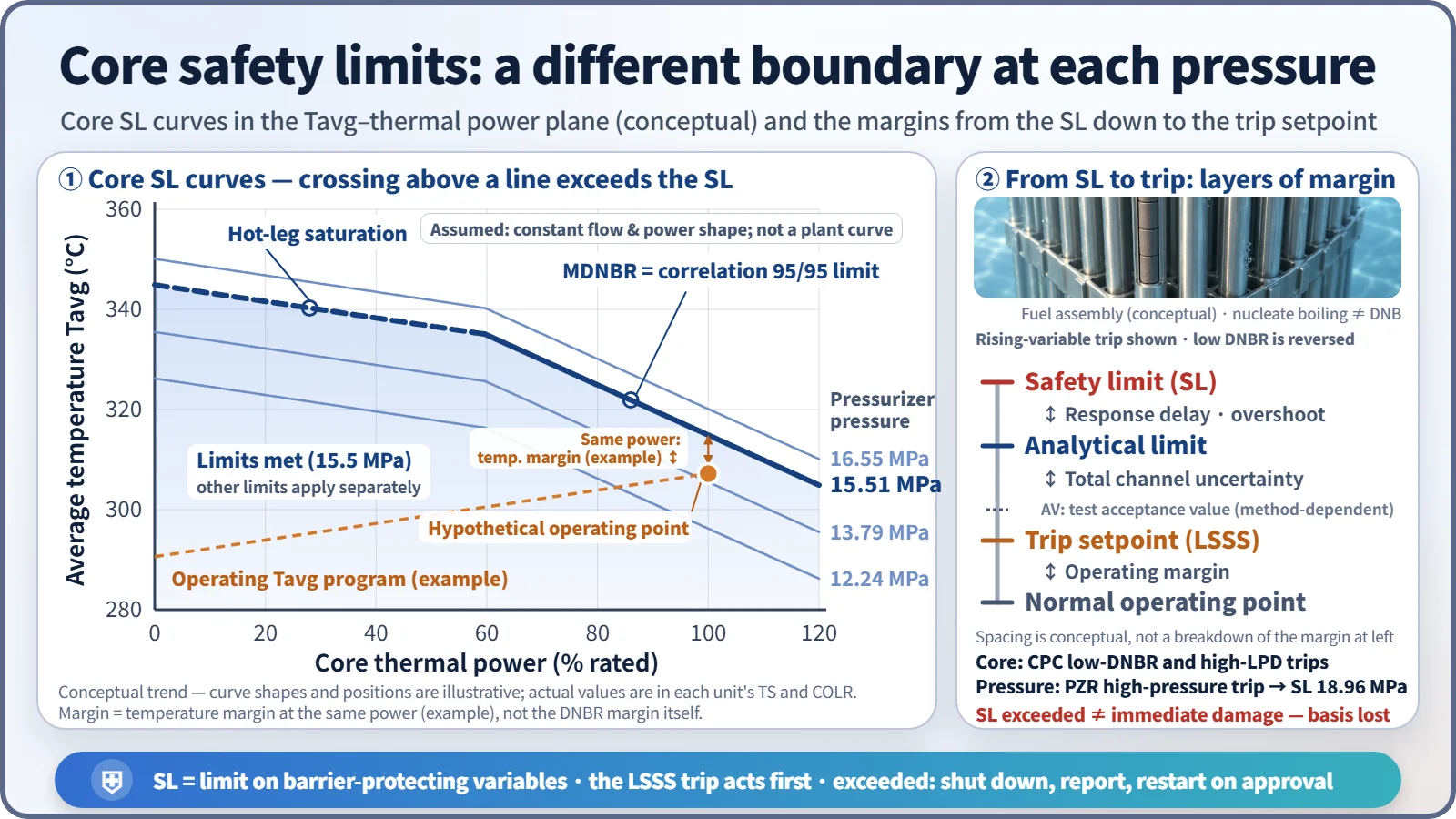
Older Westinghouse-type Technical Specifications gave the core SL as curves combining thermal power, pressurizer pressure and average coolant temperature (Tavg) (Figure 2.1-1). Each pressure curve is the locus of points where the MDNBR equals the safety-analysis limit, or where the average hot-leg enthalpy equals the saturated-liquid enthalpy. At low power the hot-leg boiling (saturation) condition sets the boundary; at high power the DNB condition does. At lower pressure the saturation temperature falls, so subcooling at the same Tavg is smaller and boiling and DNB begin earlier — the curve moves down. The hot-leg saturation condition also preserves a premise of the protection system, namely that the measured ΔT is proportional to core power. Improved Technical Specifications replaced this with numerical clauses such as "DNBR ≥ limit" or moved the curves to the Core Operating Limits Report (COLR).
RCS pressure SL — why 2,750 psia?
ASME Section III requires overpressure protection to keep the pressure boundary at or below 110 % of the design pressure. The APR1400 RCS design pressure is 2,500 psia (17.24 MPa), so the SL is 2,750 psia (18.96 MPa). Normal operating pressure is 2,250 psia (15.51 MPa). Westinghouse-type plants write the same value in gauge pressure as 2,735 psig. The purpose is to ensure the RCPB withstands the pressure without plastic deformation or failure. If it fails, the loss of coolant threatens core cooling and two barriers at once.
Even in the most severe overpressure transient (loss of load, turbine trip and so on), the pressurizer high-pressure trip and the overpressure protection valves must keep peak pressure below the SL. Instead of pressurizer safety valves, APR1400 has four pilot-operated safety relief valves (POSRVs); according to public conference material, their opening setpoint is 2,470 psia. Overpressure in low-temperature modes is handled by low-temperature overpressure protection (LTOP).
The margin between the SL and the LSSS
10 CFR 50.36(c)(1)(ii)(A) requires the LSSS to be chosen so that "automatic protective action will correct the abnormal situation before a safety limit is exceeded." Below the SL there are therefore several layers of margin.
- SL ↔ analytical limit: the transient overshoot, as the variable keeps rising during the response delay after the trip signal
- Analytical limit ↔ trip setpoint: the total channel uncertainty, combining process measurement, sensor, instrument and drift
- Allowable value (AV): the acceptance criterion used in surveillance, placed in between; its position depends on the setpoint methodology (RG 1.105)
- Setpoint ↔ normal operating point: avoiding spurious trips from everyday fluctuation
For variables where an increase is dangerous (such as pressure) this order runs from top to bottom; for variables where a decrease is dangerous (such as low DNBR) it runs from bottom to top.
In OPR1000 and APR1400, the core protection calculator (CPC) low-DNBR and high-LPD trips protect the core SL, and the pressurizer high-pressure trip protects the pressure SL.
What it means in a plant
- Design: the safety analysis shows that MDNBR, centerline temperature and peak pressure stay within the SLs for every AOO. Design-basis accidents (LOCA and so on) are evaluated against separate acceptance criteria (10 CFR 50.46 and others), not against the SLs.
- Operation: operators do not watch the SLs directly; they monitor the LCO parameters (pressurizer pressure, cold-leg temperature, RCS flow, axial power distribution) and the CPC margins.
- When an SL is violated (Section 2.2 of a unit's Technical Specifications, STS structure): core SL violated → Mode 3 within 1 hour. RCS pressure SL violated → in Modes 1 and 2, restore pressure and be in Mode 3 within 1 hour; in Modes 3–5, restore pressure within 5 minutes. Shutdown, reporting and restart only after approval are regulatory obligations (for example, in the US under 10 CFR 50.36, with restart requiring NRC approval).
Regulatory and design criteria
The criteria below are examples from US NRC regulations and Standard Technical Specifications and from the ASME code.
| Basis | Key point |
|---|---|
| 10 CFR 50.36(c)(1)(i)(A) and (ii)(A) | Definition of SL; shutdown, notification and no restart before approval when exceeded; definition of LSSS |
| 10 CFR 50.72 and 50.73 | Notification and Licensee Event Reports (LER) for power reactors |
| GDC 10 and 15, ASME Section III | SAFDLs, RCPB design limits, 110 % overpressure limit |
| NUREG-1431 and 1432, Section 2.0 | SL clauses and 2.2 violation actions |
Early editions of the Standard Technical Specifications had provisions in Section 2.2 such as notification within 1 hour and a report within 30 days, but these were dropped from later editions because they duplicated the rules (50.72 and 50.73). The wording therefore differs between editions.
Easily confused pairs
| Safety limit (SL) | Limiting safety system setting (LSSS) | Limiting condition for operation (LCO) | SAFDL | |
|---|---|---|---|---|
| Nature | Limit on variables protecting a barrier | Setpoint of automatic protective devices | Minimum function and performance of equipment | Allowable fuel design limit |
| Position | The last line | In front of the SL | Initial conditions of the analysis, available equipment | Design stage |
| If departed from | Shutdown, report, restart on approval | Trip, ESF actuation | Actions within completion times | Design not acceptable |
| Example | MDNBR ≥ 1.29, 2,750 psia | Pressurizer high-pressure and low-DNBR trips | DNB parameters, SITs | No DNB, no centerline melting |
Nor is the SL the actual damage limit. The 95/95 criterion and the 110 % limit are conservatively chosen design limits, so exceeding an SL does not mean the fuel has failed. Still, the premises of the analysis have been broken, so the plant goes through shutdown and approval.
Key points at a glance
- Definition: limits on important process variables needed to protect physical barrier integrity (for example, US 10 CFR 50.36(c)(1)).
- Core SL (Modes 1, 2): MDNBR ≥ correlation 95/95 limit (e.g. APR1400 1.29); peak centerline temperature < melting limit (decreasing with burnup).
- Basis: GDC 10 SAFDLs — no DNB and no centerline melting in AOOs.
- RCS pressure SL (Modes 1–5): ≤ 2,750 psia (18.96 MPa) = design pressure 2,500 psia × 110 % (ASME III).
- Purpose: assure RCPB integrity and prevent loss of coolant threatening several barriers at once.
- Protection: LSSS (CPC low-DNBR and high-LPD trips, pressurizer high-pressure trip) + POSRVs + LCOs.
- Margins: SL – analytical limit (transient overshoot) – trip setpoint (channel uncertainty, AV criterion) – operating point.
- If violated: core → Mode 3 within 1 h; pressure → Mode 3 within 1 h in Modes 1–2, restore within 5 min in Modes 3–5 → report → restart after approval.